Updated-
Thanks Sam's advice. It is much easier to use Rhino than Blender in this section, so I put the easier part in front to save time. However, it is recommended to have a look the whole article. Some detail may help.
Also, Thanks Sky helps me a lot and John checked each point!
______________________________________________________
To create your file as normal in Illustrator. Remember to set it in actual size.
Download Rhino ( Free beta version in Mac now!! Oh ya~)
Open your file.
Move mouth to commend line. Type "select all"
Type "group"
Type "extrude curve"
Set the value for height
Like this!
Export into .STL
Down!
______________________________________________________
When creating a complicated curve, people who is familiar with Illustrator and Photoshop might prefer to use the pen tool in 2D softwares than in 3D environment. In brief, you just need to save your vector file as a .svg file at 2D applications, then you should be able to import it at any 3D applications, extrude the height and export it as a .stl model. (*1)
It seems to be easy, however, things are never as smooth as I expected. After failed many many times, I would like to re-organgize the methods step by step with some tips. Hope it will be help for you.
Open your .ai file in Illustrator and check following steps to reduce the chance of failure when generating G-code.
1.Try to simplify anchor points.
Using as less points as you can. Make sure there are NOT two points at the same place.
Some points are unnecessary.
Simplified path
2.The path cannot be overlapped.
Once the curve has been extruded to a 3D model, overlapped path would become crossed faces. Of course, it cannot be printed out properly.
It looks fine in 150%
In fact, the curve is overlapped after zoom in.
3.Group all separate paths in once.
Do not add extra filters or pathfinder. Do not group your design repeatedly.
Press "V" to select mode
"Ctr+A" to select all-->Press the R key-->"Group"
Releasing compound paths first if needed. Press the R Key-->Release compound path
All above preparation are in avoid of failure when Slicer generating the G-code. This is what happened to me all the time. :-(
Save your vector files into .svg files
File-->Save as-->Format(drop box)-->SVG
Converting .svg files into .stl model files by Blender
1.Open Blender
Delete the default box.
Press the right mouse button to select the box.(the edge become orange means being selected.)--> Press speed key "X" to delete it.
2.File-->import-->svg files-->choose your file
It looks like nothing in the file. Don't worry. It is too small to see. Press the right mouse button to select the center of the screen. -->Press "S" n drag the mouse to enlarge it roughly. -->Press the left mouse button to confirm.
3.Change the origin of the object
When the object become seeable, you may notice that the origin is locked to the center of the screen, NOT in the center of the object. It is kind of annoying when setting exact size. Normally I will move it to the center of the object first. This is how we do:
Bottom line-->Object-->Transform-->Origin to center of the mass
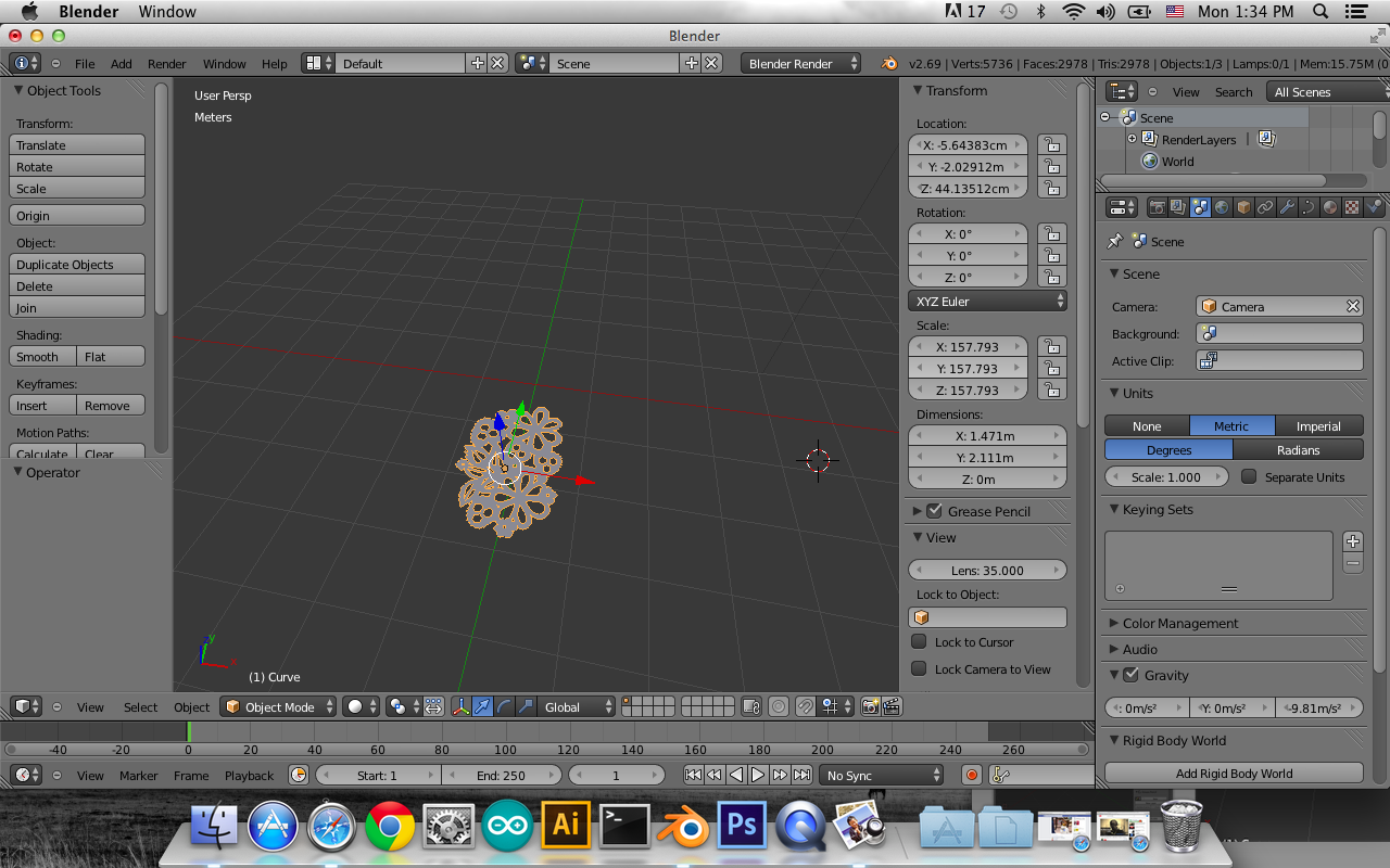
4. Set exact size
On the right side of screen-->choose the third icon "Scene"-->"Unit" --> "Metric"
5. Press "N" on screen, "Transform" table will pop out
The unit of dimension is "meter", you could press the column and insert the size you want. However, 1 m = 1 cm in actual size in Slicer. Make sure you set the right size in X and Y axis. Z axis needs to extrude first.
6. Extrude the height
On the right side of screen-->choose " curve" -->Geometry-->Extrude
7. Convert curve to mesh
Select your object-->Press "Alt+C"-->Mesh from Curve/ Meta/ Surf/ Text
If the viewpoint shading is in "Solid", we cannot see the difference. Just if you are interested, you may try the following steps to see the difference.
The bottom line-->viewpoint shading changes from "Solid" to "Wireframe"
Closer view of curve wireframe
Closer view of mesh wireframe
Now the top and bottom have been filled with faces.
8.File-->Export-->.stl file
Congratulation!!! Now your files are ready to be printed by 3D printer, or be cut by CNC finally.
Those tips are just my personal experience. I still don't fully understand some of them. If anyone would like to share your experience with me, you are more than welcome to leave comments! Let's MAKE, LEARN and SHARE!
*1 Big thanks to these useful bloggers!
Reference:
http://www.katsbits.com/tutorials/blender/metric-imperial-units.php
http://www.instructables.com/id/A-Printed-Logo-Engineered-from-2D-into-a-3D-Object/step16/Image
http://www.youtube.com/watch?v=5EOQFzsLjKI&noredirect=1
http://wiki.blender.org/index.php/User:Rayek/Doc:2.6/Manual/Interface/Units


